Thorn Me’n’U2 Electric Conversion Part 2

Some progress on the conversion.

Pedal Sensor

I’ve made a new pedal sensor rotor and sensor mount. I wanted a bigger rotor so that the sensor could be positioned outside of the radius of the tandem eccentric bottom bracket. Not knowing exactly how the sensor worked I kept the same distance between magnets, so the rotor now has 16 magnets instead of 12. The rotor is made from Tufnol as I had some, it is non-magnetic and glues well.

Test fitting the new rotor on the front crankset

The rotor bolts onto the drillings for the inner chainring. Most bikes will either have an inner chainring fitted or (for a tandem) a simple crank arm. The triplet tandem is probably unique here. I’m not sure if it makes any difference but I did make sure that the magnets are the same way round as the original rotor.

Continue reading

Thorn Me’n’U2 Electric Conversion

The bike is fantastic, however pulling a total of about 180kg up long hills leaves me worn out. It is ok until I hit bottom gear but at that point there is nowhere else to go other than leg power. We’ve always got up the hills – and I am definitely fitter and stronger than I was – but with my partner having an electric bike she has been suggesting routes that I don’t want to do due to the number of hills. I’d like to be able to ride further without worrying about the hills. I’m also curious about the kits and how they would work in practice.

So I did my research and bought a BPM kit from Woosh. Woosh have a great reputation and Andy’s patient answering of my innumerable queries has been outstanding. The BPM motor has a good reputation for lugging heavy bikes up steep hills where other motors simply melt – very important given that I’m expecting this motor to cope with pulling anything up to 250kg up 17% (1:6) hills. It is a front wheel motor; as mentioned before the rear wheel of the bike doesn’t have much weight on it and I get wheelspin on slippery surfaces with pedal power.

The kit arrived promptly and quality was good.

Continue reading

Mast partners sorted!

Figured out how to secure the mast at the partners. The rear chock now is ornamented by two bits of aluminium:

  • A plate on the bottom at the back to stop the back rising when the chock is pulled towards the mast;
  • A lashing point on the top of the block.
Rear mast chock with aluminium bits

In use it works like this:

Mast lashed in position

This is quick and easy to set up and very secure. I can lift the bows of the boat by pulling on a line to the mast top without any sign of the mast or chocks moving. As with all these things, once you figure out how to solve the problem it is easy and obvious.

Mast update

Got the mast strengthener in today. I was assuming that it would just slide in; however it jammed after a bit probably due to grit somewhere. Every time I took it out and cleaned it up (filing off the scratches) it jammed again, so I hammered it in using a wooden mallet. Fortunately it went all the way in without jamming completely. Phew.

Strengthener in with the aid of 3-in-one oil and a big hammer

I put the mast foot back on with locktite thread lock on the screws – I don’t want them coming out under sail.

Continue reading

Free standing aluminium mast – design tweaks and cutting the tubes

Right – time for a deep breath. This is where the designs become reality. First stage is check the design to get it as good as possible.
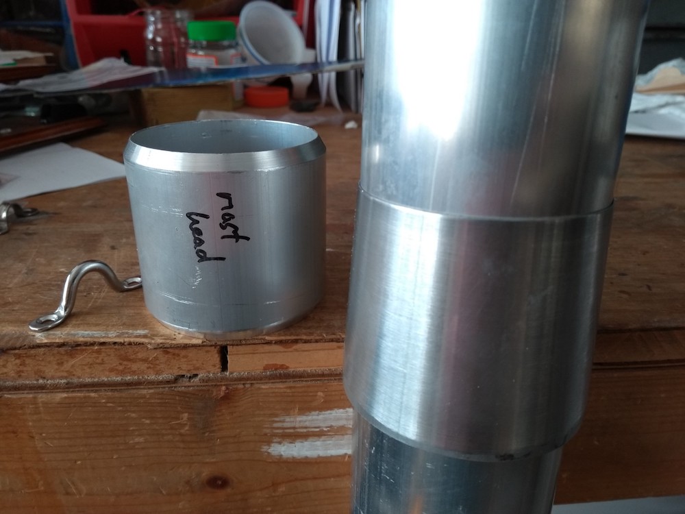
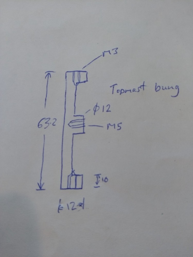
Mast head

The topmast tube needs to be extended a bit for the mast head fitting. The length for the stress calculations remains the same – 5.6m – but the overall length is a bit longer to allow for the masthead bung and the loops for the masthead blocks

Topmast

The main 2 3/4″ x 10swg tube is heavy when 5m long. To make the mast lighter where it counts I tweaked the topmast length and made it a bit longer and the main tube shorter. The trade off is that this reduces the strength at the base of the topmast. This should be ok as some of the load is distributed over the length of the mast plus as soon as the sail is reefed the load in the topmast decreases dramatically.
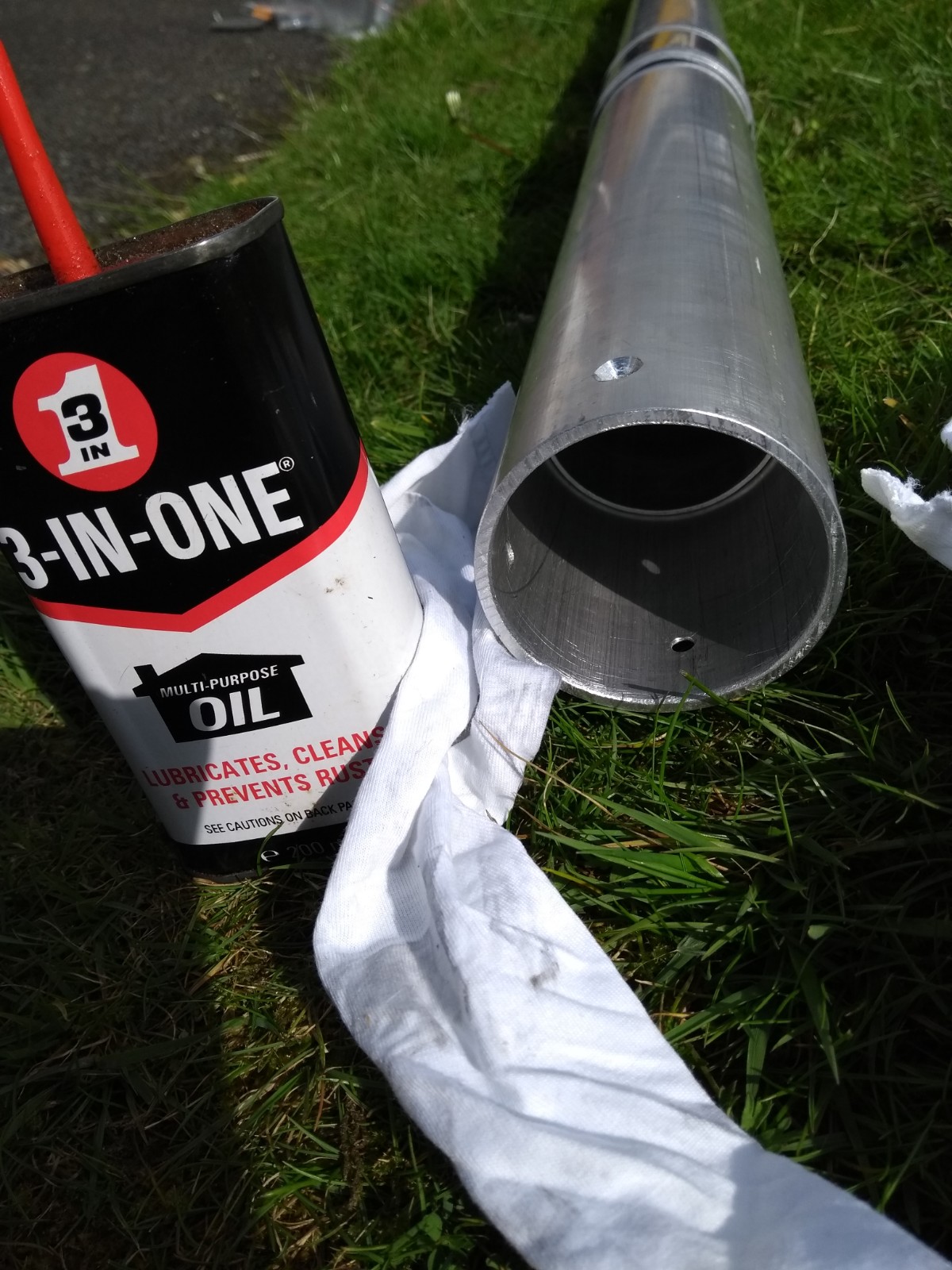
Mast foot

I’ve tweaked the design of the foot. The main tube (2 3/4″ x 10swg) will go all the way down to the heel fitting. The strengthener will stop a bit above the heel fitting. Theoretically the strengthener could stop at 395mm above the heel, but in practice I’m going to take it down to 100mm above the heel. The primary reason is that I want lots of strength at the mast pivot point.

Mast pivot

The Wanderer features a tabernacle with a pivot that makes putting the mast up much easier – a one-person job. Given that it will just be me on my own putting the mast up it makes sense to keep this feature. The similar GP14 without a pivot requires two people to put the mast up safely.

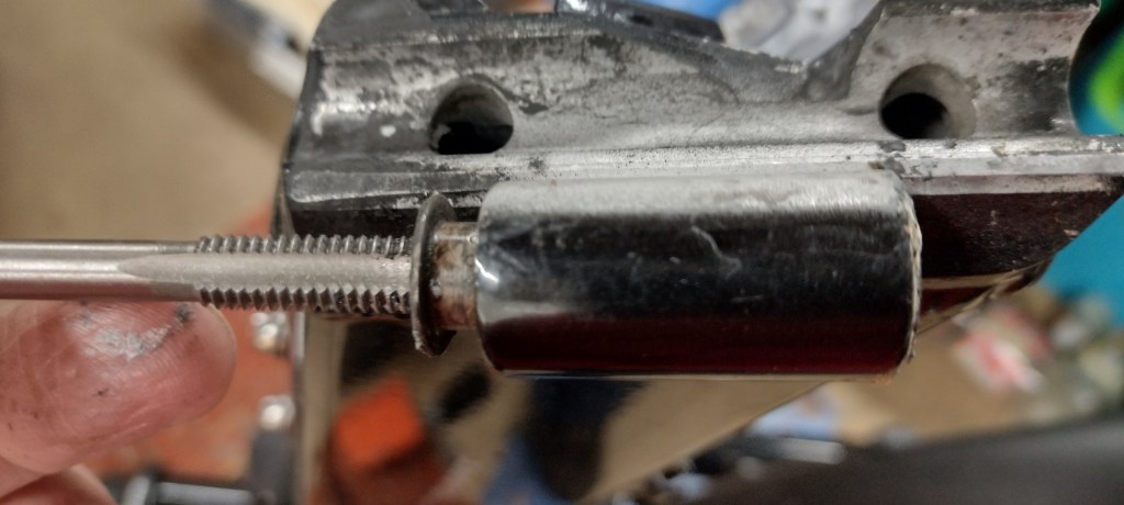
The issue is where to put the pivot on the mast tube. Drilling a hole through the tube is by far the simplest route but will weaken the mast in a highly stressed location. Ideally the pivot should be clamped to the mast but this raises other issues:

  • The mast might hit bits of boat as it goes up and down. Clearance in the hull was designed for a centre-pivot.
  • It is a lot more work unless I can think of a clever way to do it.

I’m going to reinforce the mast at the pivot point with some internal Scots Pine. This shouldn’t be too hard to do and means if I need to drill right through it should be strong enough. I need to have a play with a section of tube in the boat to find out how it will all fit together.

Continue reading

Wanderer aft cleats

One thing about sailing with small children is that you want to tie up to a jetty if at all possible. This means having usable cleats. It is possible to tie off to the traveller but having cleats is easier.

However, I don’t want the cleats to catch on the mainsheet or other ropes, This means they need to be somewhere out of the way. The best option appears to be to feed the rope through the handhold at the back of the side decks and forwards onto a cleat under the side deck.

I made up two plywood panels – one for each side – and attached the cleats using T-nuts. I’ve also added some spare T-nuts for other attachments, one spare cleat (it is always useful to be able to tie things on) and a clamcleat that will take string threaded through the scupper on the transom – this can be used for a foothold rope or for attaching the tent.

Reverse of the panel with T-nuts fitted. The T-nut recesses were sealed with thinned varnish.
Continue reading