
Some of the literature on violins suggests that the shape of the cross-section of the top and back is based on cycloids. Whether this is actually true is a matter for debate. Certainly much of the shape of a violin can be generated from circles so it is certainly possible that the masters based the shape on a cycloid which is generated from circular geometry. However, some modern makers say that they shape the top until it looks right rather than until it matches a template, so requiring the shape to fit precise geometry is probably requiring too much precision from the process.
Regardless, here is a script to generate the shape of the top of an arch-top string instrument using curate cycloids. I’ve written it in Python. I’m not experienced in Python so please excuse any errors and let me know how it could be better in the comments below.
The script takes in a PNG file that holds the shape of the long-arch down the centre of the instrument, plus the shape of the edges of the curved section. Using a PNG to hold this information means you can generate these curves however you like.
Note that the shape of the edges is the edge of the curved section, not the edge of the instrument nor the location of the ribs. On a violin this means this curve excludes the corners at each end of the C-bout.
Example file, generated from the SVG curves on MakingTheViolin.com:
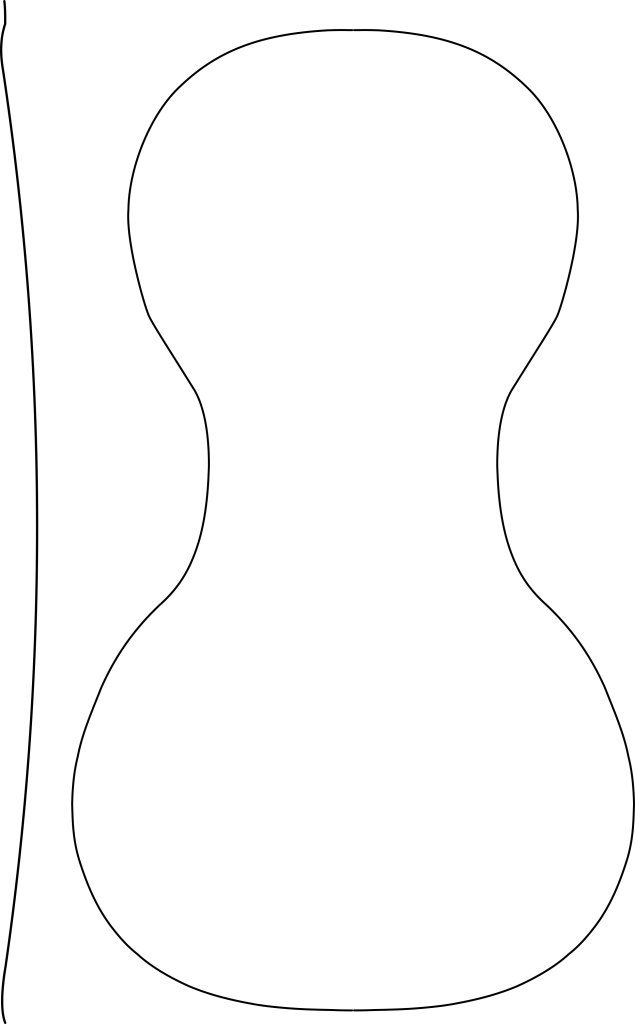
The height of the long arch is measured from the left-hand-side of the image so make sure that the image starts at the base of the long arch. If the PNG image isn’t correct then the script will produce the wrong output or maybe no output at all, so use the –debug and –verbose flags to work out what is going wrong.
Run the script using
python3 cycloid.py makingtheviolin-sides-and-centre.png points.xyz
Parameters include:
–ratio r: The ratio between the constants a and b in the cycloid formulae. Defaults to 0.3; can be 0 < r <= 1.0. Larger values produce a wider curve down the centre of the top or back.
–verbose: Turns on verbose output; useful if it isn’t working.
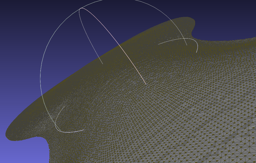
–debug filename: Writes a points file containing the edges and long curve of the shape. Very useful to determine whether the script is reading your PNG correctly. Import this file into MeshLab to see what is happening.
If all goes well you’ll have a point cloud that you can import into MeshLab to create a surface for further work.
The script is provided in the hope that it will be useful, but I don’t guarantee it will work for you 🙂 I’ll try to provide support if you comment below.
"""
Script to calculate a point cloud over the surface of a stringed instrument.
The points are calculated using a curate cycloid or trochoid.
See https://en.wikipedia.org/wiki/Cycloid

MakingTheViolin (http://www.makingtheviolin.com/Arching) mentions
that the cross-sections of violins can be generated using cycloids. There
is debate as to whether the surface of a violin can really be modelled
as a cycloid; however it seems likely that a cycloid is fairly close
to the required shape given that many modern makers carve the
shape so that it looks right rather than to any fixed template.

However, note that this assumes that each cross-arch is a cycloid.
The major cross-arches may well be cycloids; however many of the
cross arches of the upper and lower bouts of the instrument
should probably be taken radially rather than purely at
right-angles to the centreline. As such this script can only
produce an approximation of the shape.

The script takes the long arch down the centre of the back and
the shape of the sides of the instrument from a raster image file
e.g. a PNG. This allows flexibility of generating the shape as
long as that shape is simple enough to be modelled in a purely
x-y fashion.

The script looks for 'darkish' lines against a white background.
Notably inkscape will produce transparent backgrounds and the script
doesn't recognise these, so ensure that there is a white
background using the
Document Properties/Background/Background colour
setting.
"""
from enum import Enum


def trochoid(phi, a, b, f):
    """
    Returns a point (x,y) on a trochoid given phi, a and b
    :param phi: Angle of rotation of circle. Must be in radians
                (2pi is full circle)
    :param a: The radius of the circle that is being rotated
    :param b: The radius of the point that we're following. If a==b
              then we've got a cycloid. The ratio a/b governs the shape
              of the output.
    :param f: The magnification factor for the y return value. Used to get
              the maximum y value correct.
    """
    import math
    x = a * phi - b * math.sin(phi)
    y = f * (a - b * math.cos(phi))
    return x, y


def is_a_line(pixel):
    """
    Returns True if the RGB value darkish
    :param pixel: pixel[1] is the red component of the colour,
                  pixel[2] is the green component of the colour
                  pixel[2] is the blue component of the colour
    :return: True if darkish
    """
    return pixel[0] < 200 and pixel[1] < 200 and pixel[2] < 200


class EdgeState(Enum):
    """
    States used in the measure_to_edge() function
    when reading the PNG file.
    """
    FIND_Z = 0
    FOUND_Z_LINE = 1
    FIND_FIRST_EDGE = 2
    FOUND_FIRST_EDGE_LINE = 3
    FIND_SECOND_EDGE = 4


def measure_to_edge(filename, verbose):
    """
    Reads the distance from the PNG file.
    :param filename: The file containing the arch and outline to measure
    :param verbose: True if verbose output should be printed
    :return: A list of tuples;
             0 is x - the width of the body,
             1 is the y of the measurement down the image
             2 is the z-height of the centre of the body at that point.
    """
    from PIL import Image
    edges = []
    with Image.open(filename) as img:
        # Image.getPixel() API is slow but easy to understand
        mode = img.mode
        if not mode.startswith("RGB"):
            raise Exception("Unknown mode " + mode + " in file " + filename + "; file cannot be read")

        # Work out the scale in dots per mm
        dpi = img.info.get("dpi")
        dots_per_mm_x = dpi[0] / 25.4
        dots_per_mm_y = dpi[1] / 25.4

        x_max = img.width
        y_max = img.height

        for y in range(0, y_max):
            if (verbose):
                print("Line ", y)
            state = EdgeState.FIND_Z
            data_x_start = 0.0
            data_y = y / dots_per_mm_y
            data_z = 0.0
            for x in range(0, x_max):
                pixel = img.getpixel((x, y))
                if state == EdgeState.FIND_Z:
                    if is_a_line(pixel):
                        data_z = x / dots_per_mm_x
                        state = EdgeState.FOUND_Z_LINE
                        if verbose:
                            print("Found z at ", data_z)
                elif state == EdgeState.FOUND_Z_LINE:
                    if not is_a_line(pixel):
                        state = EdgeState.FIND_FIRST_EDGE
                elif state == EdgeState.FIND_FIRST_EDGE:
                    if is_a_line(pixel):
                        # Store starting pos to work out width
                        data_x_start = x / dots_per_mm_x
                        state = EdgeState.FOUND_FIRST_EDGE_LINE
                        if verbose:
                            print("Found first trochoid edge")
                elif state == EdgeState.FOUND_FIRST_EDGE_LINE:
                    if not is_a_line(pixel):
                        state = EdgeState.FIND_SECOND_EDGE
                elif state == EdgeState.FIND_SECOND_EDGE:
                    if is_a_line(pixel):
                        # Work out width to return
                        data_x_end = x / dots_per_mm_x
                        data_x = data_x_end - data_x_start
                        # Add to edges
                        edges.append((data_x, data_y, data_z))
                        if verbose:
                            print("Found second trochoid edge")
                        break
                else:
                    raise Exception("Unknown state when looking for a line")
    return edges


# Main routine
if __name__ == "__main__":
    import math
    import argparse

    # Parse the command line arguments
    parser = argparse.ArgumentParser(description="Generates a point cloud for an instrument front or back")
    parser.add_argument("-d", "--debug",
                        help="The name of an optional file to contain debugging points")
    parser.add_argument("-v",
                        "--verbose",
                        help="Write information about what is happening to the console",
                        action="store_true")
    parser.add_argument("-r", "--ratio",
                        help="Ratio between a and b in cycloid formula; default is 0.3",
                        type=float,
                        default=0.3)
    parser.add_argument("measurements",
                        help="The name of the file to read containing the measurements")
    parser.add_argument("points",
                        help="The name of the file to write the point cloud data to")
    args = parser.parse_args()

    if args.ratio <= 0 or args.ratio > 1.0:
        print("--ratio must be greater than 0 and less than or equal to 1")
        exit(1)

    # Measure image to find side edges
    edges = measure_to_edge(args.measurements, args.verbose)

    # Create a debugging point cloud showing what we've measured
    if args.debug:
        with open(args.debug, "w") as debug_file:
            for edge in edges:
                edge_format = "{x:.2f} {y:.2f} {z:.2f}\n"
                length = edge[0]
                x_dist = length / 2.0
                debug_file.write(edge_format.format(x=0.0 - x_dist, y=edge[1], z=0))
                debug_file.write(edge_format.format(x=0.0 + x_dist, y=edge[1], z=0))
                debug_file.write(edge_format.format(x=0, y=edge[1], z=edge[2]))

    # Point cloud of the trochoid curve
    points_file_format = "{x:.2f} {y:.2f} {z:.2f} \n"
    with open(args.points, "w") as points_file:
        for edge in edges:
            x_edge_length = edge[0]  # Distance across back
            x_edge_offset = x_edge_length / 2.0  # Centre of back is at zero
            y_edge_position = edge[1]
            z_max = edge[2]

            a = x_edge_length / (2 * math.pi)  # One revolution of circle
            b = args.ratio * a  # 0.3 seems about right for ratio of b/a
            f = z_max / (2 * b)  # Factor to get the height right
            z_comp = f * (a - b)  # Offset in z above zero
            phi = 0.0
            number_of_points = 100
            increment = math.pi / number_of_points
            limit = math.pi * 2.0 + increment / 2.0
            while phi < limit:
                x, z = trochoid(phi, a, b, f)
                points_file.write(points_file_format.format(x=x - x_edge_offset,
                                                            y=y_edge_position,
                                                            z=z - z_comp))
                phi += increment

    # End
