
You may have heard of Ukulele Acquisition Syndrome (UAS). I’ve got Ukulele Construction Syndrome (UCS). I need to make another ukulele.
I want something that is definitively a ukulele, but a bit different. So how about an archtop pineapple ukulele?
Here’s a basic design:
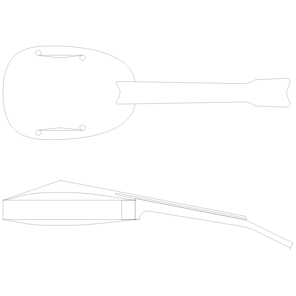
This is basically the same shape as a standard pineapple ukulele; however, the bridge needs to be somewhere in the middle of the soundboard – say 50mm from where it would normally be – so the neck needs to be around 50mm longer to compensate. From the front it will look like a long-necked soprano.
I’m trying to follow violin design principles, so the thickness of the top, the size of the bass bar (bracing) and the break angle over the bridge will match the violin. At this stage I don’t think it will have a sound post:
- The back of the ukulele is against the player which will damp resonance;
- It would be very hard to get the soundpost in from the F-holes due to their size and location.
Instead I’ll add an extra bass-bar – probably a bit bigger than the bass-side bar as the treble side needs extra rigidity.
Materials
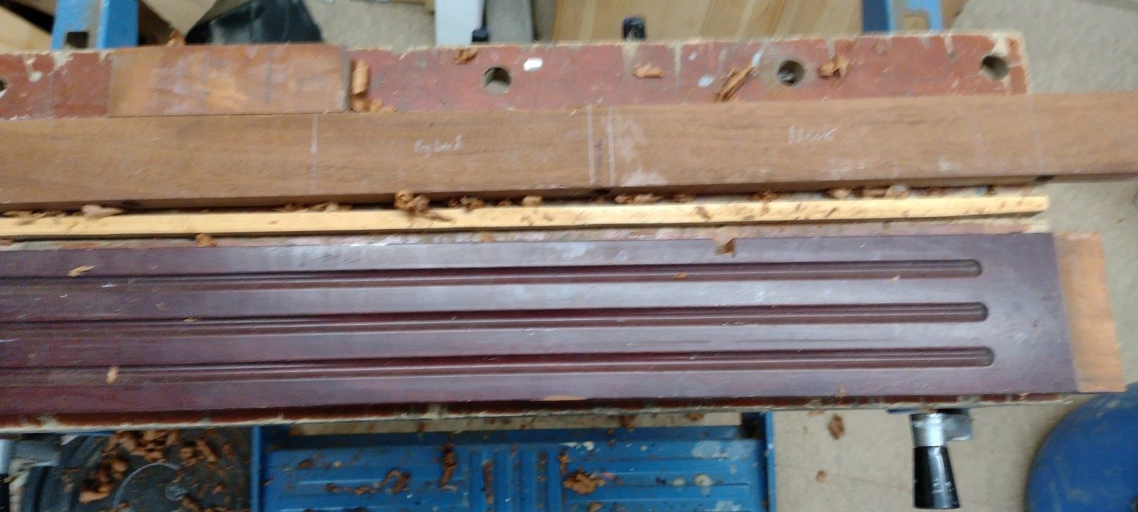
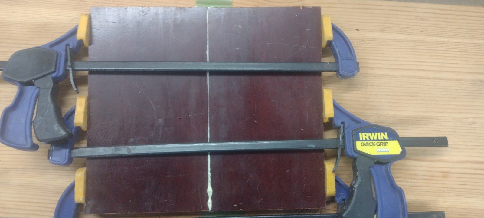
The material will be mahogany – in this case a 1980s fireplace surround. The wood has a good tap tone and the grain seems good. The salvagable bits are just big enough for a ukulele or maybe two.
I was hoping to use walnut for the fretboard and bridge; however my parquet floor tiles are too short for the fretboard on this ukulele. I do have some iroko; it isn’t easy to work as it tears easily and the dust is toxic but Internet research suggests it sounds good.
Carving
My dad gave me a Mostics 3018 CNC router – he couldn’t get it to do anything useful. In some ways the machine seems nicely made – well finished – but it is very flexible and the bearings are sloppy. This means that it tends to vibrate a lot and the bit can be a few millimeters from where it should be.
With a slow enough feedrate and small enough cuts it works ok; however this means that making a soundboard can easily take 10 hours. I don’t have that kind of time – I need to be able to complete a cut in maximum 4 hours to be viable. It isn’t easy to break up longer cuts. Thus I invested a bit of time in working out the fastest settings that yielded resonable results.
My conclusions were:
- The machine will cope with a 6mm shank cutter (up from the default 3mm)
- A flat ended end-mill in HSS with two flutes seems to work well. I also tried a ball-nose tungsten cutter. I think that the HSS is a bit sharper (really matters on this machine) and the corners of the flat end cut much better than the centre of the ball.
- Cutting with the grain in conventional milling works very nicely permitting speeds of up to 900mm/min. However this loses lots of time returning to the start of each cut.
- Zig-zagging with the grain works ok – the machine is alternately in conventional and climb milling which produces a poor finish (due to the slop in the machine) but doesn’t waste time returning to the start. Feedrates in the range 600-800mm/min.
- Cutting cross-grain at any speed is to be avoided where possible.
- Depth of cut of 2mm is ok both in depth and across the cutter.
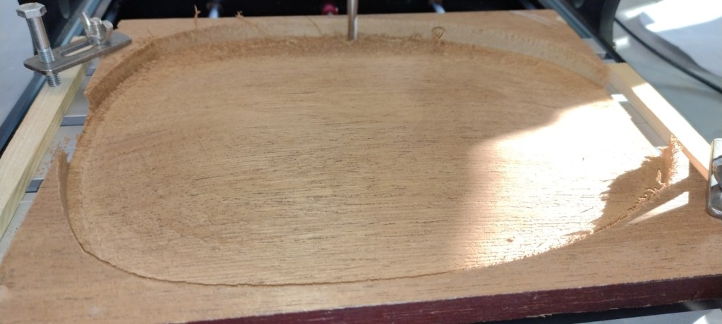
Tuning everything as far as possible I can rough-cut a soundboard in about 3 1/2hrs. A finish cut takes about 1 1/2hrs. I can then easily finish by hand using a cabinet scraper.
A 3018 machine will cope with something 30cm long and 18cm wide. The front and back are about 25cm long and about 18cm wide – rather tight. The biggest issue I have yet to solve is making sure that everything is in the right place before cutting out the back of the soundboard – there isn’t much room to play with and any error is critical. If the machine does hit a limit it carries on, but now cutting in the wrong place so setup is very important to make sure no limits are hit.
Software
To operate a CNC machine I need software to:
- Generate the design that I’m trying to make;
- Convert that design into GCode that tells the machine the path to follow;
- Sends the GCode to the machine and manages the cutting process.
Commercial software is available but I’m doing this on zero budget so my toolchain is:
Inkscape & QCad for 2D design. Inkscape handles bezier curves very well; QCad is good for precise work.
Blender for 3D design. Blender isn’t great for general CAD but is good for items where you want something to look right. This matches the requirements for designing instrument soundboards rather well.
BlenderCAM to convert the Blender design into GCode. This works very nicely overall. The paths seem accurate and sensible.
Universal GCode Sender to send the GCode to the CNC machine and manage the cut. Nice software.
I have also written some GCode directly. If you know exactly where the tool should be then this is the easiest approach. I’ve written code to mark out a fretboard this way.
Some pictures
Update 8 February 2023
The Mostics 3018 CNC spontaneously dismantled itself while machining the soundboard 😦

I have been pushing it fairly hard so maybe it is my fault. However the design is terrible – what I’d call optimistic – it works if everything goes well. In this case one of the screws that holds the collet holder in place came out (probably into the vacuum cleaner) and the collet holder then started bobbing up and down. This meant that the tool dug in causing the X-axis to miss steps hence the hole. Memo to self – every screw needs Loctite to cope with the vibration. The collet holder itself is poorly designed as the hole onto the motor shaft has slop meaning the cutter never rotates concentrically but instead can bounce back and forth. I’ll need to glue that in place too.
While sorting out the collet holder I figured I would try to reduce the slop in the Z-axis. I ordered some longer linear bearings but while taking the thing apart I noticed this:
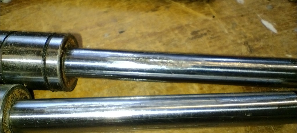
Big gouges out of the Z-axis slides. I guess one of the linear bearings has seized so has been tearing holes in the rods. No wonder it was loose! So I’ve ordered some replacement rods too.
I’m wary of putting too much money into a poor machine – in many ways it would be better to just buy a much better CNC router – but this needs to be done as cheaply as possible for now.
Update 17 February 2023
The new bearings and slides arrived quickly.

They are far better than the originals – no play that I can detect. The bearings are 10mm longer which helps rigidity but reduces Z-axis travel. I can live with that. The shafts are 100mm instead of 90mm which means they stick out of the top a bit but this doesn’t have any negative effects.

I also added a bearing at the bottom of the Z-axis leadscrew. I’m not sure this makes any difference but it was cheap and easy to do.
To try and avoid the machine dismantling itself again I filed flats on the leadscrews where the grubscrews contact.
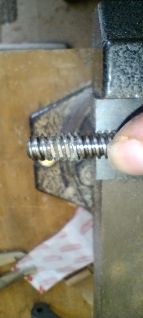
This should make it harder for the shafts to rotate in the shaft connectors. I also put Loctite on all the screws; particularly the grubscrews as these would be damaged by overtightening.
I filed flats on the motor shaft under the grubscrews and used Loctite to secure the collet holder to the shaft. It isn’t concentric but at least it doesn’t move around now.
I installed a roughing endmill. These are designed for quickly cutting steel leaving a poor finish. Being HSS they are very sharp and fairly cheap. On the 3018 reducing the cutting force is critical and this new cutter certainly slices through the wood. The finish from the end of the endmill is good; it is only the sides that leave a poor finish. If only the collet chuck was concentric. Sigh. I have measured the motor shaft and it is spot on; however I can’t adjust the collet chuck to provide acceptable runout.
I’ve still got major issues with the software – BlenderCAM can generate spurious paths sometimes – but hopefully I’m getting those sorted now.
Next stage is to follow the instructions here and here to get the machine optimised a bit. I’ll write this up when done.

Pingback: DIY Pineapple Concert Ukulele | Martin's Blog