
I want a cambered sail for the advantages it gives us – better performance particularly close to the wind. There are disadvantages for ocean travellers – the sail can flap about in light winds and swell – but these don’t affect a dinghy (hopefully!).
This is my approach to calculating how to make the sail. There are others, and there may be errors in my calculations – if you spot any please let me know.
If you want to skip the maths there is a spreadsheet that you can plug the basic figures into. The maths is just to explain what the spreadsheet is doing – for me as much as anyone!
Update: before you build anything from this please read subsequent posts:
These cover tweaking the edges of the cloth to get good shape in the forward part of the panel.
I’ll be using a barrel-cut sail to make the camber. This is where the panel is one piece with curved edges like a barrel stave. It is simple, works fine and doesn’t appear to cause any creases as long as there is a bit of stretch in the cloth on the diagonal. It also means that I might be able to flatten the sail by stretching the sail along the battens – not sure if this will work in practice but we’ll see.

The camber profile I’m going to use is the NACA 4-Digit series. A good description of some of the aerofoil profiles available is here: https://people.clarkson.edu/~pmarzocc/AE429/The%20NACA%20airfoil%20series.pdf.
The 4-Digit series is notable for having good stall characteristics. This is very useful – it means that our sail is more likely to work ok at strange angles to the wind; i.e. in gusts or with helm error.
Hang on – an aerofoil is 2-sided and this is for a one-sided sail?
Correct. I’m going to solve that problem by ignoring it. The sail I made a couple of years ago using this profile works very well indeed so in the absence of something better I’ll do this one the same way. Arguably the sail should have a more rounded luff but for now lets go with this profile.
The profile is given to us as a set of coordinates in a text file. I’ve imported them to a spreadsheet to generate the rest of the data I need.
The inputs to the spreadsheet are:
- W – chord of the sail section. This is the length of the centreline of that panel.
- Hp1 – the height of the sail panel at the luff
- Hp2 – the height of the sail panel at the leach
- i – Angle of incidence; the overall angle of the panel to the batten. This will be something like 15º for a split-junk jiblet or 0º for a main panel.
- Cpercent – Camber in %; the depth of the maximum camber expressed as a percentage of the chord.

As an output I want the dimensions of the extra cloth I need to add to the edge of the sail panel to generate the right camber: yextra for each value of x; from the NACA data file. I want the camber on the centreline of the panel to match the profile I’ve selected, and the camber will get less as it gets nearer the (more-or-less straight) battens.
My main assumption is that the sail will form a circular section. This is on the basis that the air pressure on the downwind side of the sail is generally less than the air pressure on the upwind side, which will inflate the sail like a ballon. Other people have assumed a catenary curve; however the maths is much easier for a circular section and this appears to give the expected camber for my previous sail.
So here goes.
First off I want to generate the X-coordinate for my cloth. That’s easy – I multiply the NACA X figure by the chord.

The Y-coordinate will be broken down into steps. First I want to know the extra cloth I’m going to need for the jiblet angle.

Basic trigonometry yields:

where:
- Ei is the extra cloth to add in for the angle of incidence;
Thus:

Now for the desired camber. This will be the NACA camber figure for the X-coordinate scaled for the desired camber percentage, multipled by the chord of the panel, plus the extra for the angle of incidence.

Where did the 6 come from? Good question! My NACA data is from a 12% camber aerofoil. This is a symetric aerofoil, so a single side of that shape has 6% camber. So I divided by 6 and multiply by my desired camber to get the correct target figure. This isn’t the official way to calculate the profile for a given camber figure but given all the other approximations in a junk sail it is good enough.
Now we know how far the middle of the sail should be blown out by the wind we need to work out how much fabric to add to the edges.
Next work out height of the panel at the X-coordinate.


where:
- Hpx is the height of the panel at the point we’re interested in;
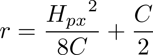
I can now work out the radius of curvature of the sail, assuming that it is a circular section. Wikipedia is our friend here: https://en.wikipedia.org/wiki/Arc_(geometry)#Arc_radius

Putting the Wikipedia equation into our symbols:
Now the radius has been calculated we can work out the included angle $theta$ and thus the length of the arc, which is the amount of cloth we need to get this camber.


This is cool – I can now generate the correct length of cloth to give me the required camber between battens at any angle.
To transfer these figures to cloth I’m going to draw the panel out on paper (cheap lining paper or wall paper). The easiest way I’ve found is to draw up the panel with straight edges, then add the curves along the straight edges using a small ruler. So I need the amount to add to the straight edges:

I’ve put all this in a spreadsheet to make it easy to use. The input cells are in yellow; the output cells are in orange. As with all spreadsheets there may be errors so please check and let me know!
There is a final correction to make. The sail cloth will follow a curved line along the camber, whereas the battens are (more-or-less) straight. This means that the cloth needs to be a bit longer than the battens. I may end up with some wrinkly batten pockets but that’s ok.
To work out how much longer it needs to be I’ve simply added up the distances between each edge point down the sail. The difference isn’t much on a 2m long panel – around 30mm for 12% camber – but I may as well try to get it right. This correction is the final column in the spreadsheet.
Updates:
- Moving hosting to wordpress.com has broken the equations plugin. Sorry! I’ll redo the equations manually when I get a chance. (Now done!)
- Moving hosting also dropped the spreadsheet. I’ve reloaded this with my current version which incorporates compensation for the stretch on the bias making the leading edge better.

Hi… This is great that you have this all laid out! I tried the links for the spreadsheet, but was not successful. I wonder if there is another way to see that? Thanks for putting this up – it’s really helpful!
Best wishes,
Shemaya
LikeLike
Oops – that got lost in the site migration. I’ll try to sort it ASAP. I do have some tweaks to the spreadsheet and I’ll try to get them posted.
LikeLike